| View previous topic :: View next topic |
| Author |
Message |
zefarelly
Registered User
Joined: 26 Nov 2007
Posts: 91
|
 Posted: Fri Oct 24, 2008 7:46 am Post subject: Posted: Fri Oct 24, 2008 7:46 am Post subject: |
 |
|
why did I paint my axle casing . . . 2 radius arms looks like the way to go
I have a pair of escort ones on the shelf which are of no use  I also have bracketry for them I also have bracketry for them |
|
| Back to top |
|
 |
calex_fr
Registered User

Joined: 18 Jul 2008
Posts: 408
Location: Champagne (France)
|
| Posted: Fri Oct 24, 2008 8:29 am Post subject: |
|
|
Whaoooooo, I just start to understand !
(I think you complicate things unnecessarily, Olympic is not a Ferrari).
Well, perhaps Phase One is like this :

Phase Two like that but with one control arm :

My car is a normal phase two, like Joe :

  |
|
| Back to top |
|
|
calex_fr
Registered User
Joined: 18 Jul 2008
Posts: 408
Location: Champagne (France)
|
| Posted: Fri Oct 24, 2008 8:29 am Post subject: |
|
|
| zefarelly wrote: |
why did I paint my axle casing . . . 2 radius arms looks like the way to go
I have a pair of escort ones on the shelf which are of no use I also have bracketry for them |
what exatly do you want to do ?
_________________
Alexandre Contat
from France |
|
| Back to top |
|
|
Dave-M
Registered User
Joined: 20 Jan 2006
Posts: 377
Location: Yorkshire, England
|
| Posted: Fri Oct 24, 2008 11:53 am Post subject: |
|
|
Continuing on from the drawings I posted earlier.
Rod, the single link to the diff housing top was my initial thought but I decided not to go that way for 2 reasons. a) the distance from the axle c/l would have to be greater than from c/l to lower link. b) there is a possibility of clearance issues on full bump.
Paul, well written and very understandable and most helpful.
Here are a few thoughts to explain why I am going with the layout as in my drawing.
On the phase 2 shell there is a boxed in area just behind the front mounting position (for the trailing links) you have used on your Phase 1 and the top link would have to pass through this and then would have clearance problems with the seats.
Hence the diff / tunnel mountings.
I want to retain the original lower arms in my car and just fabricate two new upper arms of the same length.
The problem is that they will need modifying and here is the reason (I think) the whole geometry of the botton link and damper mounting is wrong:-
Under the pressure of producing the Phase 2 as quickly as possible the trailing arms were made to the wrong dimension, the distance used was taken from the axle c/l to the front of the mounting box moulded into the floor pan and not to the pivot point.
If you look at the A, B, & C dimensions on the side view drawing you will see they are the same (well they are within 0.1").
If the traling arms had been remade shorter the pivot would have been directly below the axle and the damper would have been vertical, which is, I am sure how it was intended.
However, having found the error, and probably having a pile of arms already made, the easy way out was taken and the axle mountings were angled back behind the c/l.
Nobody complained and the fault was never designed out.
The upshot of all this is that the original trailing arms will have to be shortened at the front end by around 1.125" to bring everything back in line and the axle pivot brought forward by the same amount.
If you look at the side elevation drawing it will all become apparent.
I have ordered the Tubing and rose joints and will keep you posted.
One other advantage of the proposed 4 link layout is that it will be much kinder to the propshaft uj's. If you look at the angle of the diff at bump and droop you will notice quite a large angular change and this coupled with a very short propsahft put all the angular loads on the uj at the gearbox end. With the four link it splits the angular deflection to equal amounts at each end.
Paul, when you weighed your car what figure did you get? I have seen figures varying from 12.75 cwt (1428lb/650kg) to 17.25cwt (1932lb/878kg) and need some accurate figures to calculate the spring rates.
Regards
Dave
Last edited by Dave-M on Fri Oct 24, 2008 1:13 pm; edited 1 time in total |
|
| Back to top |
|
|
Dave-M
Registered User
Joined: 20 Jan 2006
Posts: 377
Location: Yorkshire, England
|
| Posted: Fri Oct 24, 2008 12:07 pm Post subject: |
|
|
| calex_fr wrote: |
Whaoooooo, I just start to understand !
(I think you complicate things unnecessarily, Olympic is not a Ferrari).
|
Alex, I agree it is not a ferrari but when you do your first track day you will find all the problems.
Because my car is being rebuilt and I can do these things to improve it that is what I will do.
I think it is worth talking about don't you, as we all share these ideas our knowledge and understanding increase and we may be able to have our Olyimpics as they were supposed to be.
Regards
Dave |
|
| Back to top |
|
|
calex_fr
Registered User
Joined: 18 Jul 2008
Posts: 408
Location: Champagne (France)
|
| Posted: Fri Oct 24, 2008 12:15 pm Post subject: |
|
|
Yes I agree with you.
Can you do it simply and quickly ?
 
_________________
Alexandre Contat
from France |
|
| Back to top |
|
|
calex_fr
Registered User
Joined: 18 Jul 2008
Posts: 408
Location: Champagne (France)
|
| Posted: Fri Oct 24, 2008 2:04 pm Post subject: |
|
|
| Dave-M wrote: |
Continuing on from the drawings I posted earlier.
Rod, the single link to the diff housing top was my initial thought but I decided not to go that way for 2 reasons. a) the distance from the axle c/l would have to be greater than from c/l to lower link. b) there is a possibility of clearance issues on full bump.
Paul, well written and very understandable and most helpful.
Here are a few thoughts to explain why I am going with the layout as in my drawing.
On the phase 2 shell there is a boxed in area just behind the front mounting position (for the trailing links) you have used on your Phase 1 and the top link would have to pass through this and then would have clearance problems with the seats.
Hence the diff / tunnel mountings.
I want to retain the original lower arms in my car and just fabricate two new upper arms of the same length.
The problem is that they will need modifying and here is the reason (I think) the whole geometry of the botton link and damper mounting is wrong:-
Under the pressure of producing the Phase 2 as quickly as possible the trailing arms were made to the wrong dimension, the distance used was taken from the axle c/l to the front of the mounting box moulded into the floor pan and not to the pivot point.
If you look at the A, B, & C dimensions on the side view drawing you will see they are the same (well they are within 0.1").
If the traling arms had been remade shorter the pivot would have been directly below the axle and the damper would have been vertical, which is, I am sure how it was intended.
However, having found the error, and probably having a pile of arms already made, the easy way out was taken and the axle mountings were angled back behind the c/l.
Nobody complained and the fault was never designed out.
The upshot of all this is that the original trailing arms will have to be shortened at the front end by around 1.125" to bring everything back in line and the axle pivot brought forward by the same amount.
If you look at the side elevation drawing it will all become apparent.
I have ordered the Tubing and rose joints and will keep you posted.
One other advantage of the proposed 4 link layout is that it will be much kinder to the propshaft uj's. If you look at the angle of the diff at bump and droop you will notice quite a large angular change and this coupled with a very short propsahft put all the angular loads on the uj at the gearbox end. With the four link it splits the angular deflection to equal amounts at each end.
Paul, when you weighed your car what figure did you get? I have seen figures varying from 12.75 cwt (1428lb/650kg) to 17.25cwt (1932lb/878kg) and need some accurate figures to calculate the spring rates.
Regards
Dave |
Dave I have translated your text, almost everything, and I began to understand!

_________________
Alexandre Contat
from France |
|
| Back to top |
|
|
Dave-M
Registered User
Joined: 20 Jan 2006
Posts: 377
Location: Yorkshire, England
|
| Posted: Fri Oct 24, 2008 3:19 pm Post subject: |
|
|
Alex have you used the Google translator?
If there are any parts you do not understand, please ask and I will try my best to help.
Dave
_________________
Ph.2 Ford 1500 GT
GT with Rochdale Chassis |
|
| Back to top |
|
|
Paul Gething
Registered User

Joined: 10 Feb 2006
Posts: 91
Location: Redditch Worcs UK
|
| Posted: Fri Oct 24, 2008 8:35 pm Post subject: |
|
|
Rod
With regard to your comment
| Quote: |
1. I suppose ,for these calculations for a damper/spring unit, we can disregard the small upper torque reaction arm as the rotated angle of the axle is irrelevant, or am I missing something?
|
With the short upper arm, you are right, the axle will rotate a great deal. It will put greater strain in the uj's on the short prop shaft and sap power through the drive train.....for me....it slows the car....for the Greens....it means that you use more power and emit more CO2 
Dave, I will pull out my little red book and have a look for the weights.
In terms of rear springs....On the PH1 they were 90lbs/in as standard, Lotus 7 were 80lb/in. I now run 160lb/in and it is fine on the road in the wet and the dry.
Although there is a difference in the leverages on a PH2 compared to a PH1 I would have thought 130lbs/in would be a good place to start.
 |
|
| Back to top |
|
|
Paul Narramore
Registered User
Joined: 13 Mar 2006
Posts: 181
Location: Aylesford, Kent.
|
| Posted: Fri Oct 24, 2008 10:40 pm Post subject: |
|
|
As a one time design draughtsman, I ought to be following this but I'm afraid it left me a while back. To me it should be a comparatively simple task. Design a rear suspension which works. Don't deviate (too far) from accepted norms so it doesn't. Leave off the rear suspension units and jack the axle up and down and watch what goes on.
However if someone actually get's a better system to work, I'll be the first to congratulate you. |
|
| Back to top |
|
|
calex_fr
Registered User
Joined: 18 Jul 2008
Posts: 408
Location: Champagne (France)
|
| Posted: Sun Oct 26, 2008 11:48 am Post subject: |
|
|
Paul Gething,
is your car ?


_________________
Alexandre Contat
from France |
|
| Back to top |
|
|
Paul Narramore
Registered User
Joined: 13 Mar 2006
Posts: 181
Location: Aylesford, Kent.
|
| Posted: Sun Oct 26, 2008 3:11 pm Post subject: |
|
|
The simple swinging arm you have drawn looks far better than the chunking great effort found on the Ph2, however I can't see it would work.
What you propose is that the bottom of the suspension unit would have a ring instead of a pin mount. What happens when (say) the nearside wheel rides up over a kerb? The tyre/wheel will rise up and the suspension will compress. What happens to the bolt which goes through the bush in the ring mount? It cannot twist and I doubt if there would be enough give in the bush. It works on a motorcycle because the swing arm only moves in one plane, whereas on a Ph2 it must swing about it's pivot as well as from side to side.
Another thing. By using a simple square section bar, you've lost about 4" (100mm) as the suspension unit has to sit on top of the swinging arm. To recover this, the top mounting in the bodyshell would need to go up 4" too.
Can you see the difficulties?
Yes, that's Paul's car.
PS I've put this reply on the wrong thread too (damn) or have I. What happened to the CAD drawings? |
|
| Back to top |
|
|
Paul Gething
Registered User
Joined: 10 Feb 2006
Posts: 91
Location: Redditch Worcs UK
|
| Posted: Sun Oct 26, 2008 6:19 pm Post subject: |
|
|
Oui, Alex. cela est ma voiture. C'est un Phase1.
Un autre photo

Mon autre voiture.....Le meilleur laxatif connu.........

Le même virage comme le Rochdale est photographié. |
|
| Back to top |
|
|
TonyS
Registered User

Joined: 17 Jan 2006
Posts: 230
Location: Worcestershire
|
| Posted: Sun Nov 02, 2008 10:41 am Post subject: |
|
|
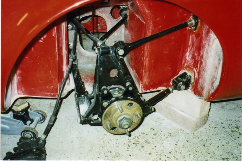
Rear Suspension "DUFFY"
Last edited by TonyS on Thu Jan 01, 2009 9:39 am; edited 1 time in total |
|
| Back to top |
|
|
Paul Narramore
Registered User
Joined: 13 Mar 2006
Posts: 181
Location: Aylesford, Kent.
|
| Posted: Sun Nov 02, 2008 11:58 am Post subject: |
|
|
Tony
I like the race car simplicity of Richard Parker's front and rear suspension on Duffy. Compared to the standard Ph2 suspension, it just looks as if it works OK. Of course the old engineering maxim was "If it looks right, is usually is right". |
|
| Back to top |
|
|
|

