MAGAZINE No 105 SPRING
2006
Bristol Classic Car Show Report
Our stand at the show this year show was organised
with the benefit of our experience last year and we asked for, and got, a
better position. This was not a lot warmer than last year, but a small heater
made things bearable and we were on one of the main through ways. As a result,
we had a very busy time, possibly one of the best ever, with a steady stream of
visitors to keep us occupied. I reckoned the time of year and the cold weather
ensured that only proper enthusiasts attended. Coupled with the informal
atmosphere and easy access this made for an enjoyable experience.
Derek Bentley had kindly volunteered to help with the
setting up and he and Roger and I had booked into the same B&B as last year
and had the usual welcome - very cosy - which softened the impact of doing a
show in the middle of winter.
We had space for two cars (just) and had the usual
Olympic, courtesy this time of Colin Ellis, and Roger Coupes Riviera. A small
Gazebo and a couple of display boards completed the stand. We also took the
opportunity to hold a committee meeting, thankfully in a heated part of the
venue the organisers office.
Roger had been volunteered to give one of the
talks/demonstrations by club exhibitors that went on each day. He showed how
he made his paperweights in the form of Rochdale cars and I for one found it
interesting and instructive. It was a pity that these demonstrations were not
better publicised, as they were poorly attended even Rogers!
Many thanks to Colin and Roger for the display cars,
and the other members who volunteered to help man the stand for cheerfully
enduring the chilly conditions. See you there next year? Hope so.
Alan Farrer
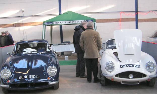
A quiet time on the stand
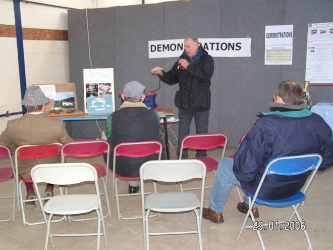
Roger
had one of the biggest audiences
EVENTS FOR YOUR
DIARY
AGM - 2 April (see page 1)
South Midlands
Monthly Classic Car/Bike Meet 12 March, 9 April, 9 May (see page
9)
Guy Stallards Spring
Start Up 23 April (see page 10)
Stoneleigh 06 Kit Car
Show - Sun 30 April/Mon 1 May (see page 9)
Prescott Hill Climb
Open Classic Car Event 2005 - 13/14 May (see page 11)
Cheshire Kit and
Classic Car Show & Rally at Capesthorne Hall 21 May (see page 4)
Classic LeMans - 7/9 July see website for
details www.lemansclassic.com/uk/ind
Royal International
air Tattoo, RAF Fairford, Glos - 15/16 July (see page 9)
Historic Specials Day at Burford - 13 August, organised
by the FSCC (date to be confirmed).
CAPESTHORNE WEEKEND 2006
Cheshire
Kit and Classic Car Show & Rally.
Sunday May 21st 2006 (10am to
4.30pm)
BE THERE!
We had a most enjoyable weekend last year, despite
slightly iffy weather, so we hope to see even more of you and particularly your
Rochdales this year, and that the weather will be good. The event is now open
to classic cars so, if your Rochdale isn't ready yet and you have a classic,
bring that along instead.
How can you help? We need helpers on Saturday
afternoon (20th) at about 2.00pm to erect our HQ tent, place various signs
around the estate roads, layout the public car park entrance, mark out the Kit
Car display area, mark out stall holders pitches, fix signs "to the
show" at strategic points around the approach roads, put out refuse bags
around the display areas etc.etc. I don't know if the sheep will be returning
this year but a trowel or shovel is a useful item to have with you just in case
- many hands make light work.
After the setting up has been completed circa 5.00pm
we shall be having a non-damaging driving test competition for the Rochdale
Motor Panels Trophy, this being competed for each year at Capesthorne with a
fun driving test competition in a Rochdale. For those of us who haven't got our
Rochdales on the road, last year was a great opportunity to re-familiarise
ourselves with the cars and demonstrate our judgement skills, thanks to the
generosity of those who allowed us to take part in their cars.
For the evening we shall be going to the same pub as
last year for a hot meal after which there will be a talk on a motoring topic.
For catering reasons we must know how many are going to be
present on the Saturday evening please let Roger Coupe (tel 01606 889384)
or myself (tel 01332 690680) know if you are coming and how many - otherwise
there is a risk there won't be a free meal for you!
On the Sunday your organisers and committee look
forward to seeing as many of you as possible together with your Rochdale or
Classic if you can bring it (unrestored cars on trailers are equally welcome!),
to ensure we all enjoy a companionable club day. If you have any ideas for
activities on the day or would like to help your club, please contact either of
the organisers before the day. It gives us much more confidence if we are
assured of a minimum number of helpers before the event.
On the day please report to the HQ tent when you
arrive so that we know you are around and perhaps we may even have a small task
for you! Remember this is your club and without the success of this event we
would find it almost impossible to carry on financially.
The reputation of this Show continues to grow and
grow, but we cannot maintain this reputation for the Show without YOU!
Finally, remember to bring this magazine with you to gain
free entry to the show.
Look forward to seeing you there,
Ron Scarfe (Show Co-ordinator)
(NB Capesthorne Hall is on the A34 about 16 miles
south of Manchester and 5 miles West of Macclesfield, and is 1mile south on the
western side of the A34 after the A537/A34 crossroads known as Monks Heath,
Capesthorne Hall caravan site 01625 861779 or in office hours 861221. Local
accommodation: Macclesfield T.I.O. 01625 504114 or Congleton T.I.O. 01260
271095).
Chair
Chat.
Well our Club has reached a milestone in its history.
This year marks the 25th anniversary of the
formation of The Rochdale Owners Club.
Back on the 7th of June in the summer of
1981 at a Limited Edition car gathering on the Melbourne Loop at Donnington
Park, a group of Rochdale enthusiasts put the wheels in motion to set up the
club as we know it today. I wonder if any of our present members can recognize
the cars in the photographs? It is interesting to note that the first club
magazine was published in the October of that year. So maybe we should do
something to recognize this milestone in our club's history. I think you might
find this as an agenda item at the forthcoming AGM. So please come prepared
with your ideas and suggestions.
Above and next page: Where it all started -
Donnington Park 7 June 1981
This year got off to a good start for the club with
the Bristol Classic Car Show. It was a very cold two days, but the company was
very convivial and there was a lot of interest from the public. Many thanks to
Alan for organizing the club stand, it's a date I will be fixing in my diary
for next year, that's for sure.
On the home front there has been a little progress on
"Sows Ear", but not much to see at first glance. Most of the time
has been spent on widening the track to fill out the rather wide Mk 6 wheel
arches. This has been achieved at the front by widening the split axle hinge
points. That meant I had to remove the transverse leaf spring and fit coil
springs similar to the set up on the Halifax Chassis on my Riviera. My next
task is to prepare the drive unit. This will consist of a Ford 100E Engine
fitted with an Elva O.H.I.V. head and Shorrocks Supercharger. The gear train
will be a period Ford 3 speed box fitted with Buckler close ratio gears
and a 4.7 back axle.
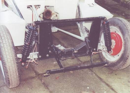
Sows Ear front end widened and converted to
coil-overs
Coming back to club matters, the next date for our diary is
the AGM on the first Sunday in April (April 2). It is always good to see so many
members and their cars, even though the pre-Olympics are still very thin on the
ground.
Then on May 20/21 we have the Cheshire Kit and
Classic Car Show. As ever the Saturday is developing into a great opportunity
for club members to get together in the afternoon to set up the show field and
take part in a driving test. This gives members a chance to have a drive in
different cars. Then in the evening we will once again be going to a local
restaurant for a meal and a chat.
I think you will find more details of both the above
events elsewhere in this mag. so I look forward to seeing
you then.
Roger.
**************************
Spares Note
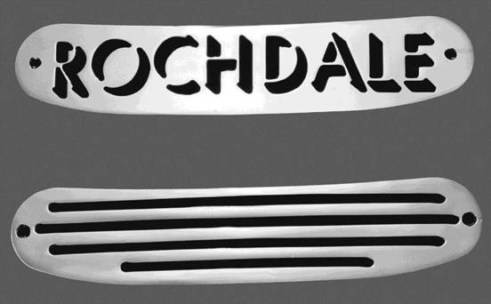
Club member Derek Farrow has had some grilles made to
cover the air intake at the base of the windscreen. They are made in chrome
plated brass and are pictured below. If you are interested, please contact me
with a view to getting a batch made. Prices will be £15 for the slotted design
and £20 for the Rochdale one.
 Nigel
Nigel
Olympic Phase II subframes
There has been a lot of discussion recently about Phase II
subrframes, as quite a few of them are reaching the end of their useful life,
and it has been very strongly suggested that the club should be manufacturing
replacements. At the recent committee meeting, there was a discussion covering
the main points, summarised below:
The originals frequently have different angles of camber and/or
castor on each side. This was hopefully a fault of inaccurate construction
rather than the original design.
Richard Parker is on record as saying that if he was doing it
again, he would design out the antidive by making the wishbones parallel
The original design used tubular steel of dubious quality
should a better quality be used for the tubes?
The
original design used spacers as a cheap method of both widening the track and
allowing a change of pcd. This is unsound engineering. Alloy hubs are now available
in any pcd required. However, have any cars experienced problems as a result
of using spacers?
On
the inner ends of the wishbones, the Rochdales have 1/2" diameter threaded rod,
whereas the original Triumphs used 3/8" bolts supported at each end. This
means that the Rochdales experience greater wear on the bushes as there is no
inner steel sleeve.
There is no facility for camber adjustment on the Rochdale.
If
the club manufactures a subframe of any type, but in particular if it is
significantly different to the original, where will we stand legally on product
insurance? Will we need to get the design tested by an independent qualified
engineer?
Some members, notably Colin Breakspear and Ron Collins and Peter
Bissett have produced subframes which have parallel wishbones, and use the
Triumph uprights. These seem to work well.
The original subframe jig has completely disappeared.
There had been very little (ie 1) response to the Editors plea
for input from the membership, although it was felt that if they were
available, more interest would probably be forthcoming.
It was therefore felt, as a first stage, that we should
measure as many original subframes as possible.
Derek Bentley has volunteered to produce a CAD
drawing of the subframe from these measurements. Once we had the relevant
dimensions, then we could decide whether to produce drawings for members to
use, or make the subframes as a club spare, and if this option was chosen,
decide what specification to use.
What do you think? Please let us know; come to the AGM and
make your views known.
Alaric
TONY STANTONS
EVENTS PAGE
The Royal
International Air Tattoo, RAF Fairford, Gloucestershire 15 & 16 July
The Royal International Air Tattoo is Europe's premier
air show featuring static and aerial displays of classic and modern, military
and civilian aircraft. This year's theme reflects the ability of the Armed
Forces to react quickly and decisively to events around the globe with the
theme of "Speed" taking centre stage. More details about the
Air Tattoo can be found online at http://www.airtattoo.com
This year, for the first time, we are including a
Vehicle Display dedicated to interesting vintage, classic and modern vehicles
of all types. This will be on one of the hard-standings normally used to park
aircraft. There will also be an exclusive area nearby for the use of anyone
displaying a vehicle.
We are pleased to offer a free pass to the Air Tattoo worth
up to £35.00 to anyone displaying a vehicle for one day or two free passes,
allowing a passenger to attend free, if the vehicle is displayed on both days.
Additional passes may be purchased at the normal rate of up to £35.00 (This is
the "on-the-gate rate", the sooner you buy them the cheaper they
are).
There are a few minor restrictions:
For health and safety reasons vehicles being
displayed must be in the display area from 7:30am until 7:30pm on each day.
Pre-registration is required along with details of the
vehicle, registered keeper, driver and any passengers. Passes will be
non-transferable. Passes issued will only be valid when accompanied by the
vehicle.
If you would like to display one or more of your
interesting vehicles please contact:
Tony Stanton e-mail tony-stanton@fsmail.net
STONELEIGH 06 KIT CAR
SHOW 30 April & 1 May
The worlds number one show for every kit car enthusiast
with old or new kit cars.
Tony Stanton has reserved stand No 39D with
which he intends to promote cars built before 1973. The stand is entitled:
HISTORIC SPECIALS AND
CLASSIC KIT CARS
Entry: Free for kit/classic car and driver Half
price for passenger
Entrance is via the main vehicular entrance (follow
yellow signs for clubs) which is located on the B4113 Coventry to Leamington
Spa road.
For more details contact Tony Stanton (as above)
South Midlands
Monthly Classic Car/Bike Meet
The second week of every month at Britannic assurance Plc, 1
Wythall Green Way, off Middle Lane, Wythall , Birmingham B47 6WG (on A435 1
mile north from M42 J3). Sunday 12 March, Sunday 9 April, Tuesday 9 May,
Tuesday 13 June
Social Club will be open for drinks. BBQ (weather
permitting) on the lawns. Wildlife park to walk round. Room for up to 1000
cars.
For more details contact Tony Stanton (as above).
Letter from Tony Wright Phase 1 779 CUG
Two things firstly I enclose details of the
Cheltenham & Cleeve Vale Rotary Club Classic Hill Climb event on 13/14
May. There is plenty to see in a fantastic historic venue with the chance of a
run at the legendary hill. It would be great to see Rochdales there; could you
mention it in the next magazine? OK
The second item involves me in an almost dreamlike
situation. Circumstance took me to a pretty cottage at the end of a small lane
on the outskirts of Coleford in the Forest of Dean. In front of the cottage
was a grassy paddock littered with one or two semi-redundant cars and, delight
of delights, three amorphous tarpaulin shapes. I called at the house but,
finding no-one in allowed my curiosity to take over. The first was so
unremarkable I forget what it was; the second an intriguing strange boxy shape
that proved to be a Midget. The third had an intriguing outline that defied
easy recognition but hinted at exotic compact, low, coupe. Could it be an
Alfa SZ, Renault Alpine or something even rarer? With trembling fingers I
lifted the brittle tarpaulin - the exotic blurring with erotic and their
delights - I recognised the familiar profile of an Olympic door and frame. Of
all the gin joints in all the world to paraphrase Rick.
I now reminded myself that with no owner present I
was trespassing, so just committed a few basic details to memory. These
included some body glass out, a mid-blue colour, one of my favourites - wire
wheels, a BMC lump which suggested Marina and finally no rear door which hinted
at Phase 1, but not conclusive. Finally, remembering Derek Bentley, I looked
for a registration number but could find none. I replaced the tarpaulin and
left a note at the cottage.
Subsequent contact with the owner Peter Thomas and
his wife confirmed the Phase 1 was originally registered JAC which has been
reallocated. It is for sale and Peter is on 01594 833943. During Peters
ownership it was repainted supposedly by professionals in a special boat finish
for fibreglass, but he was disappointed with the result. The car is complete
with original Riley rear axle and possibly MGB gearbox. Its condition is
compatible with standing on grass under a tarpaulin and requires energy and
persistence to return it to respectable road-going condition.
However I know we are among like-minded souls and who
would not see these issues overcoming the privilege of owning an enigmatic and
unique piece of sports car history - £650 to you squire!!
PRESCOTT HILL CLIMB OPEN CLASSIC CAR EVENT
Cheltenham Cleeve Vale Rotary Club invites classic car
owners to an event to be held on the weekend of 13th and 14th
May 2006. The event is open to all pre-1980 vehicles but exceptions may be
made at the discretion of the organisers for particularly interesting
vehicles .
Sunday 14th will be devoted to display and driving
the famous hill, with passengers if you wish, in marshalled but untimed runs.
Un-timed runs eliminate the need for crash helmets and the full gamut of safety
equipment etc. However vehicles must have valid road tax, MOT and insurance
documentation. The entry fee will be £20 per car and parking will be in the
Paddock
This year we will be developing a static display in a
designated area of the Orchard for classic, vintage and special
vehicles. We are also proposing to hold gentle cavalcade parades up the hill
so that they can be displayed in motion to the attending public. We feel this
will greatly enhance the presentation of the superb range of vehicles
expected.
Static entrants have a reduced entry fee of £10 which will
include a cavalcade parade.
On Saturday we are offering a 50 mile Cotswold tour starting
and finishing at Prescott, and in addition there will be a dinner/buffet at
Prescott Lodge. Both events will be subject to a minimum participation number
and are open to all entrants.
Block bookings by Clubs will be particularly welcome and we
will endeavour to park such groups together on Sunday. Spectators will be
welcome at £10 per car with free car parking and pedestrian access to the
Paddock etc. All profits will go to Charities supported by Rotary. In order to
maximise this we are asking for your cooperation to treat the entry fee as a
donation to charity under gift aid so that we can reclaim tax.
Following the press report of the 2005 event in Practical
Classics we suggest that to avoid disappointment, early booking is made on the
entry form*.
Organisers: Bob Price 01242 232527 & Geoff Kimber 01242
602643
* Contact me if you want a copy of
the entry form, or contact one of the organisers directly - Ed
A Subframe Saga
Anyone owning a Phase 2 Olympic will know about
rusting subframes and the associated repair problems (not only Phase 2 Russ!
Ed). My Phase 2 is no exception. It was built in 1973 and I believe had
been off the road since 1980. I acquired the vehicle from Tony Stanton in 2001
and was eager to restore it and get it back on the road. The strip down was
hard work but went without problems. I knew that the subframe was not
serviceable and managed to remove it for repair with the help of a Dremel and a
mini angle grinder that I purchased for the task.
The subframe was in a worse state than I had first
thought. Much of the lower portion had rusted almost to dust where it had been
glassed in. My first decision was to repair it to original, rust treat it and
glass it back where it came from. Talking to various people around the club
made me realise that certain things would be better changed before refitting
it. One of the changes that I decided to make was to dispense with the hub
spacers. This meant that the wishbone mountings would need to be further
apart. I cut the frame in two thinking that it would be a simple job to weld
in repair sections of tube.
Because the frame was now in pieces with some of the
lower half missing I made a jig to position everything correctly. A local
machine shop made lower wishbone mounts for me and I put these in the jig along
with the salvageable bits of the frame. Doubting my welding skills I entrusted
the repair to the welding instructor at the college where I worked. I provided
drawings and photos to help with the task. Months passed without progress and
he told me that he was having trouble sourcing the materials. I retrieved the
jig and bits and decided to think again.
It was now a case of giving the work to a specialist,
but who? It needed to be someone close by or else I would have to trailer the
body shell to someone like Keith Hamer. The project sat for some time while I
pondered what to do. Retirement came for me with its associated tightening of
the belt and I even thought of selling the car.
Fortunately I managed to get a part time job back
with the college and they had a new welding instructor. I did not want to go
through the same cycle as before with him but he encouraged me to invest in a
TIG welder and have a go myself. I purchased a second hand TIG welder but it
blew all the fuses in the house. I discovered that it was only suitable for an
industrial power supply and changed it (adding significantly to my bill of
course) for a more modern inverter unit. That worked well and I started
practising on bits of scrap. When I felt competent enough I went out to source
material for the job. The problem I found was that steel stock holders were
not prepared to supply the small quantity that I needed. I resorted to scouring
the area for steel fabricators using the sort of tubing I needed. I could not
find any using round section tubing so decided to build the subframe out of
square section which was available. (I must be lucky as there is a metal
stockist near me who holds lots of round and square ERW tube and sheet and
plate and is happy to sell small quantities - Ed)
After several materials forays I had a small stock of
mild steel plate (3mm and 1,5mm) and two lengths of square section tube (20mm
and 26mm). I was unsure of the strength of the tubing I had acquired, or of my
welds, so decided to make extensive use of gussets in the frame. I made a
start by joining upper and lower wishbone mounts using 20mm square tubing. I
next joined left and right suspension mounts using 26mm square tubing. Because
my jig was made of wood I tack welded bits in place then removed them from the
jig for the finished weld. I fabricated the spring/shock upper mountings from
1.5mm plate and welded these in place. I now had all of the front suspension
mountings in the correct relative positions but needing structure.
At this point I made another change of plan. There
has been a lot of talk about bolting the subframe to the body shell rather than
glassing it in. This has certain merits but would need some large plates
incorporated in the design to spread the load. If I made the subframe out of
plate I would not have to add anything to bolt to the body shell. I also felt
more confident in welding a strong structure this way.
The subframe has to fit the shape of the body shell
which is quite complicated so I spent a lot of time making cardboard patterns
and doing mock ups to get things right. I made two more jigs to sit on the
garage floor and hold the subframe in the correct position. The subframe is
now finished and looks rather like the original design plated over. The next,
and very tricky, job is to fasten it to the body shell.
My plan of action is to grind the body sections
reasonably flat where the subframe is to be fixed then cut the body shell to
form two flaps from the front part of the engine bay. I have allowed about
10mm clearance between the frame and the bodyshell, the idea being to position
the subframe correctly using my jigs then move the loosened bits of bodyshell
forward and bolt to the frame. After this I plan to layer up the front of the
engine bay to secure and strengthen everything. If all works well I should
finish up with a bolted in subframe giving the suspension geometry as designed.
I hope to have the wheels on the body by the summer
so that I can roll it out of the garage and make some more dust preparing for
general glass fibre repairs as needed. The shell is not too bad but there is a
lot of patching up required.
Russ Collins
18 Feb 2006
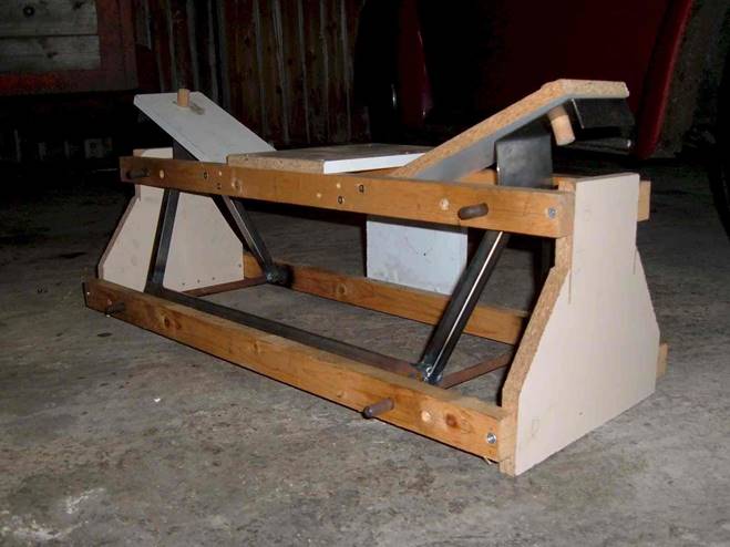
The jig with partially completed subframe Photos:
Russ Collins
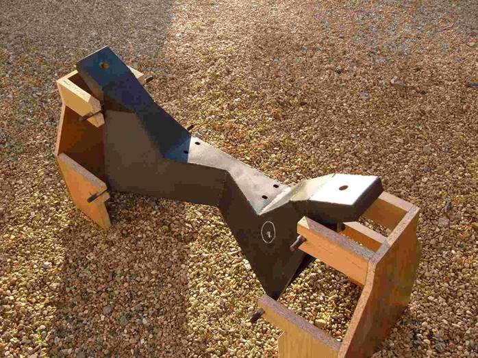
The
completed subframe resting in its jig (The chalk circle marks the
position of the hole for the steering column)
Lifespan of the Olympic Body/Chassis Unit
I have started yet another rebuild of my Phase 1 and would
value members experiences with the bonded-in steel structures even if this was
gained through scrapping an Olympic. The drawing shows the items of interest
as they relate to the Phase 1 Olympic body/chassis unit (front suspension and
steering mounting points omitted for clarity).
Many years ago I took the car off the road to repair the
bottom section of the sub-frame that had all but disappeared. I now suspect
the other tubing bonded into the GRP of the engine compartment although
applying a magnet to these areas (A) indicates that some metal/oxide
remains. Prior to repairing the sub-frame the car had been on (and off!) the
road for fifteen years, eight of these in my possession. The corrosion was
worst on the side where the battery had been sited, the weight of which had
also caused some localised creep of undershield.
In addition to the above, there are the tubes (B)
that reinforce the roof over the windscreen and doors together with the
windscreen pillars. On my car the 1" tubing is exposed over the pillar
sections and shows some rust. Also, is the tubing over the windscreen
continuous or split (C)? I know from a previous issue of the club
magazine that the Phase 2 tubular reinforcement is in two parts, presumably to
facilitate bonding into the body whilst in the mould.
Other areas of concern are the rear turrets for the
mounting of the coil-spring/damper units. There is a steel bar (D)
bonded into the GRP at the level of each platform that puzzles me. Does any
member know what purpose they serve, is it structural or was it an aid to
laminating the platforms? Both these bars are heavily corroded from exposure
in the wheel arches.
Water vapour/humidity will penetrate to the tubing over the
years through porous sections of GRP and along the interface between GRP and
tubing where bonding is poor (there is evidence of this at the windscreen
pillars on my car). If the tube ends are not sealed adequately then the internal
surface of the tubing will also be exposed to corrosion although this can be
countered by timely spaying with WAXOYL or similar, if accessible. All this of
course assumes that properly cured GRP is impermeable to water vapour at the
thicknesses of laminate considered here. It is unfortunate from a preservation
standpoint that a chemically resistant structure should have been reinforced
with a material (mild steel) that was not, but a long lifespan may never have
been the objective. I am aware that members have replaced the complete
sub-frame with their own designs and there is a plan to offer a standardised
item as a club spare for the Phase 2. Should future re-manufacture of the Phase
1 body/chassis unit ever be considered necessary then corrosion resistant metal
tubing would need to be used. In the case of the sub-frame this could also be
bolted to reinforced sides of the engine bay as an alternative method of
location to bonding into the GRP.
Before I consider my next move, which could involve the
drastic surgery that I would much rather avoid, any information on the above
would be much appreciated.
Malcolm
Lomax Phase 1 Olympic 20 February 2006
LAMINAR FLOW
By Neil Roshier
Copyright: Race Performance and Car Constructor Magazine in
Australia.
The air that we breathe is a fluid. A strange thought as
we breathe it every day and every day we think of it as a gas! This is because
a fluid does not have to be a liquid, yet liquids are fluids. confused
yet? Stay with me and we will try and make this understandable and relevant!
An excellent description of a fluid is a fluid can be
defined as: having particles that easily move and change their relative
position without a separation of the mass and that also easily yield to
pressure and are capable of flowing. So basically, for the purposes of this
article if it can flow it is a liquid and we are very interested in flow for
engines it is generally the more the better!
 The trouble is, when we read articles about flows we often
read about Laminar flow. This is where the flow is nice and stable and meets
certain conditions (more on this later) and laminar flow is most often
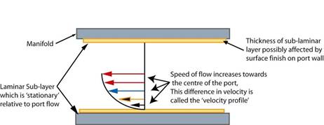
described as being layered (these are the laminas per se). With respect to
intake ports this means that layer closest to the port wall is stationary (the
sub-laminar layer). The next layer is moving quite slowly due to friction with
the sub laminar layer and the next slightly faster again and the next one the
same again etc.
The trouble is, when we read articles about flows we often
read about Laminar flow. This is where the flow is nice and stable and meets
certain conditions (more on this later) and laminar flow is most often
described as being layered (these are the laminas per se). With respect to
intake ports this means that layer closest to the port wall is stationary (the
sub-laminar layer). The next layer is moving quite slowly due to friction with
the sub laminar layer and the next slightly faster again and the next one the
same again etc.
Eventually we have the layers that are moving as fast
as they can (see image ►) It can be thought of as a series of concentric
layers, a bit like a telescopic radio aerial. The outer most layer is the sub
laminar layer and the inner most part the fastest flow with the other bits
between being the other layers.
Why Laminar flow is desirable is simply down to the fact
that it is faster, more stable and less likely to break away from the port
walls when encountering a change in direction (such as a short turn radii prior
to a valve) or imperfection (manifold/head joint). All of which means that more
air (though this aspect changes if we are using Carburettors as it will not be
just air due to the fuel in suspension) will flow through the same diameter
port at a given airspeed. For us with an engine this seems very attractive as
it will mean the engine will make more power, given all other factors being
equal.
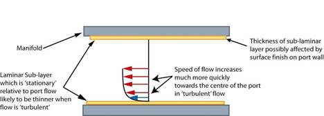 But what we must also
acknowledge is that this is a nice neat explanation of laminar port flow is
often misleading or worse factually incorrect! What we find in an intake port
is that the laminar flow as described above has always been turbulent flow.
This means that the velocity profile will be considerably different to what we
might expect of a laminar flow (see image ►).
But what we must also
acknowledge is that this is a nice neat explanation of laminar port flow is
often misleading or worse factually incorrect! What we find in an intake port
is that the laminar flow as described above has always been turbulent flow.
This means that the velocity profile will be considerably different to what we
might expect of a laminar flow (see image ►).
This change from Laminar to Turbulent occurs when the
diameter of the port, the fluid velocity and the viscosity of the fluid
(remember the bit about carburetion and fuel in suspension) creates Reynolds
numbers higher than 4000.
So now you are probably asking yourself what is a Reynolds
number?
The Reynolds number is the dimensionless combination of
variables that is important in the study of viscous flows. The Reynolds Number
is important in analyzing any type of flow when there is substantial velocity
gradient such as occurs in the intake port as described above. The Reynolds
Number indicates the relative significance of the viscous effect compared to
the inertia effect. The Reynolds number is proportional to inertial force
divided by viscous force. Reynolds Number can be expressed as:
Re = D.V.ρμ
Where:
D = Characteristic length (port diameter) μ =
Viscosity ρ = Density V = Velocity
So if we consider that some definite numbers are: The
intake port is 31mm
The viscosity of air (absolute) is often given to be
.000017894kg/m/sec (at sea level).
Density of air is often given to be 1.225kg/m3 (at sea level and
given temperature)
So what is then missing to work out the above equation is
the velocity of the intake charge. Here we come across another decision: do we
use the average velocity or do we pick the peak velocity?
However the average port flow is just that, an average. It
is made up from the lowest flow through the port (e.g. when the piston is
coming back up the bore and the intake valve is closing) to the highest flow
rate (when the intake valve is opening and the piston is accelerating down the
cylinder). Of course what we want is the most efficient intake system for the
designed purpose.
The basic measure is: laminar
if Re < 2300 transient if 2300 < Re < 4000 turbulent if 4000 <
Re
So now when we consider the flow in the intake port,
instead of having nice, stable concentric layers of flow that are relatively
discrete from each other (Laminar flow), we now have Turbulent flow. This
turbulent flow also has characteristics that are important for us to understand
as far as intake ports are concerned.
1.
Turbulent flow means energy transfer from one layer to another
due to the chaotic nature of the turbulent flow itself, either accelerating or
slowing the adjacent layer and increased surface friction.
2.
The sub laminar (layer in contact with port surface) layer is
thinner and less stable, thus it may be more adversely affected by local
conditions such as poor manifold gaps, surface irregularities and flow
separations due to too tight radii.
3.
The progression to V-max flow occurs quicker in turbulent flow
than for Laminar flow, though the V-max may be relatively lower (given the
increase in pressure drop) than for Laminar flow (it is not possible to
directly compare the overall flow of turbulent/laminar as they require
different/incompatible conditions to exist).
4.
Turbulent flow may be more disturbed by and may require greater
time/distance to recover from any disturbance, e.g. a throttle plate at 45
degrees. It was suggested to me by an engineer who works in the field of Fluid
Mechanics that often flows stabilize after a disturbance of 10 diameters (of
the port diameter). So if the port had a 22mm diameter then flow would be
stable and well formed again in 220mm.
5.
Turbulent flows may under some circumstances have beneficial
effects on fuel vaporization, though we cannot verify this from any independent
source, so don't believe it yet!
To be continued.
Minilites,
Minators and Minilights
Why are spares for some makes so much more expensive than
others? One way and another, I haven't had much to do with Vauxhalls through
my motoring career, and at £55 each quoted for hubcaps I wasn't about to change
that. Crikey, I'd just bought a set of stainless Minor items for the GT
for a fiver, so £220 to freshen up my Olympic wheels seemed a little excessive.
What were Vauxhall bits doing there in the first place? With a Riley axle and
Triumph-based front, they hardly seem the most obvious choice, but apparently
this is what many Olympics received around 1964. Couple the prices with the
fact that the Vauxhall wheels were looking decidedly skinny, and I decided to
look round for alternatives.
Classic style Minilites look good on most old cars and
similar styles have been offered by a number of manufacturers over the years. I
believe that the original Tec-Del firm had gone out of business sometime in the
70s/80s and other firms got round the copyright issue by marketing their own
wheels as Minilights (note the spelling) - the subject of legal proceedings at
one stage. Add in the re-forming of Tec-Del and similar products such as KN
Minator and you now have quite a buyers market in the UK. I was very
pleasantly surprised by some of the quotes, and eventually went for 5x13 Midget
wheels from Midland Wheel Services. In Anthracite (dark silver) and with a
polished alloy rim they looked the business, and at £200 including centre caps,
chrome nuts, VAT and postage I didn't take long to make up my mind. I figured
that with a 5" width they would fill the arches better than the originals and
was assured that with an ET20 offset they fitted a Midget easily I kept my
fingers crossed as the tyres were changed.
(ET20 means the mounting flange is
20mm outboard of the wheel centre line Ed)
No problems at the front they really improved things
but at the back clearance was much more limited, though I thought at first I
had just got away with it. Not so. It became apparent that the tyres were
rubbing as the suspension came up, and I tried grinding away at the returns on
the arches. Much of this didn't go amiss the job had clearly been very
crudely tackled when the shell was new, and I did manage to get clearance
just on the left hand side. On the right, however, the problem persisted with
the tyre (155/80 Michelins) scuffing the rear of the arch where the body
tapered inwards. Further grinding away at this point eventually broke through to
the outer surface of the body and I built up the contours with extra layers of
fibreglass. This still wasn't a good idea, however, as the tyre continued to
wear away on full bump, which seemed odd a close look at other Olympics
didn't reveal any problems, with lots of clearance. Now in the overall scheme
of things 5" isn't a very wide wheel, and it seems the problem lay in the ET 20
offset. I had never heard of this before I bought the wheels, but it apparently
represents a distance of 20mm from the mounting surface to the centre line of
the wheel and was the standard distance used by each of the manufacturers I
spoke to any more would be likely to foul on disc callipers, I was told.
There looked to be lots of clearance on the Olympic, however, and I did call
MWS again to discuss the possibility of shaving a little off the mounting
surface of my own wheels but surprise, surprise they didn't want anything
to do with it, and no, they didn't sell wheels with any other offsets. Hmm
Yes, I know it's possible to flare the arches but I really
didn't want to and neither did I want to cut them away as has sometimes been
done. Thoughts of subtle modifications to follow the original lines while
spacing them out a few mm were rejected because of the amount of work involved
and I eventually decided on replacement. Both Tec-Del and KN were more helpful
here, and I eventually took the plunge with a further set of Minators to
replace the originals - this time with an offset of ET30. The financial side
was a little less favourable this time, with a total bill, including postage of
around £256 for the four, including centre caps, postage and VAT but no nuts.
If 5" doesn't sound very wide, then a difference of 10mm
sounds even less significant, but was nevertheless enough to do the job. The
arches are now cleared even on full bump, and there is still lots of room on
the inside 1960s callipers are much less meaty than later items, it seems.
It was very difficult to see any difference between the original
MWS and new KNs without careful measurement, though it is apparent that the
wheel nuts are less heavily recessed on the KN items. I would advise anyone
thinking along the same lines to check any wheels very carefully before taking
the plunge I think even 5" width may be possible with more offset, the
problem being the distance measured in the opposite direction between the
brake drum and the surface of the tyre. This can be easily found using a
combination-type square as shown and laying the wheel, face down, on a flat
surface. The KNs + Michelins give a reading of almost exactly 2 much more
and you are asking for trouble. Of this, the tyres account for about 1/4,
giving 1 for the bare wheel. Sorry to mix the units up but hey, tyre manufacturers
have been doing it for years.

Using a
combination square on the back of the wheel to measure the protrusion of the
outside edge of the tyre from the mounting surface (brake drum). Any
more than the 2" seen here is pushing your luck. All photos by
Les Brown
Now for the silly bit. After observing a lull in E-bay
prices going up to Christmas I polished up the Minilights and took a nice set
of pictures before putting them for sale in January. This started something
akin to one of those Piranha-type feeding frenzies that you used to see in
James Bond films with 11 bids going in with quite a few above the original
price of the items! I eventually came away with £221, including postage (but
no wheel nuts) and I was left wondering why a) I hadn't done it months before
and b) folks don't check on brand new prices before they start bidding. But I'm
not complaining!
To summarise,
Riley axle + 5x13 + ET20 = BAD
and Riley
axle + 5x13 + ET30 = GOOD
The
back of the rear arches is the problem area - you may just see the wear on
the outside edge of the tyre. New Minator on the right.
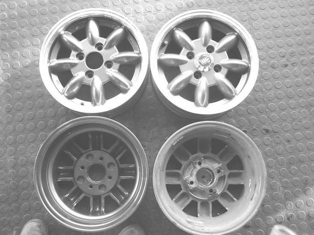
Original
MWS Minilights on the right, replacement KN Minators on the left - hard to spot
any difference.
EARLY ROCHDALES
REGISTER
Malcolm McKay
Winter's always a quiet time and I warned Alan I didn't
have much to say this time but I'm glad to say that now I've put it all
together, there's still been plenty of action on the early Rochdales front!
Aussie update
First to respond to the publication of the Register in the
last issue was Gordon Cowley in Australia thanks, Gordon, for bringing us up
to date with your very fine modified GT. Gordon writes:
The registration number is to be GT 1172. The Chassis
number is ROC 1172. The people here who had to approve the import kept asking
for a chassis or VIN number, which in my case did not exist. I told them that,
but that was not good enough. I invented the chassis number and was then
allowed to import the Rochdale GT.
I have a modified Bowden Chassis with a 105E rear axle
held in with five links and coil-over shockers. The Bowden IFS has been removed
and replaced by a Ford Ten beam axle with Mk1 Cortina hubs and disc brakes. I
have a Datsun Sunny steering box and a Mazda 808 steering column. I used the
top backing plate bolts and the specially made caliper bracket to bolt a Mk1
Escort steering arm in place for the draglink to work with. The drag link sits
over the radius rod on the LHS. The tie rod sits under the radius rods in the
usual place.
I will be using the 100E long engine that I initially
used in my 1952 Anglia Tourer. The Tourer now has a worked Ford Ten engine.
Both the engines have a modified camshaft and an external oil pump. I will be
using a Willment OHIV head. I have a split braking system and no room to fit
the twin Solex 35PHH carbies that I bought, as the master cylinders are in the
engine bay. I will be using one of the carbies with a modified single DCOE
Weber Cortina 1500 inlet manifold.
I have a 100E gearbox complete with Laycock electric
overdrive and the Rochdale GT will run on 13in Mk1 Cortina wheels. I can only
use the o/drive with second and top gear. I have a reverse light switch as well
on the gearbox and will fit the reversing lights to go with that.
I have used a Mk1 Cortina fuel tank and the spare tyre
fits on top of that. They are both behind the rear axle. I have made up a
propeller shaft hump and a cover for the gearbox and remade the engine
bulkhead. I have used fibreglass sheet, plastic body filler and aluminium strip
and angles to hold it all together. I need another layer of glass over the
bottom, interior and engine bay before paint and final assembly.
I have a three-hole instrument binnacle from a Mk1 Cortina
GT and will use an original Mk1 Cortina tacho and fuel and temp cluster with a
modern electronic VDO speedo. I have a pulse driver on the gearbox and you
can change the number of pulses per kilometre to get the speedo correct for
speed and distance. I have no gearbox cable or gearbox drive ratios to worry
about. Suzuki vans and small four-wheel drives have good nylon-bushed bits to
make remote three-speed and reverse shifters. I have internal door hinges,
electric window lifts (easier to fit than a hand winder) and Mazda 808 door
locks and recessed door handles. The interior may just be paint!
I have gone back to work, Mon to Fri, 8 til 5, so it is
now hard to find the time to finish my project. I have always been a tinkerer
and improver of cars, so I have no qualms about making my Rochdale GT of the
time that I chose (1961) with the best period bits that I could lay my hands
on and up to date in as many other ways as possible.
Thanks for that, Gordon it sounds as if you'll have a
very pleasant and usefully lively GT after all that work!
Trimming a GT
Dave Milner puts us all to shame with the work he
manages to put in on his Rochdales, despite work and family demands. His
Rochdale-chassis GT, which languished for so long in Northern Ireland and came
so close to being broken on several occasions, is now coming together and Dave
has delighted me by finally settling on a 100E engine to power the car, as
original.
He asked on the club website forum recently whether
Rochdale ever offered the GT with interior trim; it's a question that deserves
wider airing. I knew that Rochdale never offered anything, but doublechecking
my records turned up one surprise. Interestingly, the major London distributors
Super Accessories offered a Headlining and Trimming Kit specifically for the
Rochdale GT for £13, saying
Having seen so many GT saloons spoilt by poor internal
finish, we have developed a complete trimming kit comprising: -
Ready to fit Headlining (should be fitted before bodyshell
is mounted)
Windscreen Pillar Trim
Door panels covered in leathercloth
Parcels shelf for rear
Adhesive
Screws and screwcups
Leathercloth for odd trimming
Colours: Grey headlining with Blue or Dove Grey
leathercloth
To the best of my knowledge I've never seen a GT with
this trim kit, though quite a few surviving GTs have had headlining neatly
installed in the past. I do have some nice photos of period-trimmed GTs, some
really impressive. Sadly, none of these GTs survive, as far as we know and
all are different. Most of the more ambitious trimmers of the time opted for a
full-width dashboard with the instruments ahead of the driver: there was room
for this on top of the moulded dash panel and glove pockets that came with the
shell. Cutting the dash panel out was a mistake that many subsequent owners
have made doing so weakens the shell and is definitely not advisable. At
least one of the cars pictured retained the moulded glove pockets behind a neat
full width wooden dash panel with hinged lids over the pockets.
As for seats, everything from cut-down Ford Pop to
contemporary bucket seats were used and most using Ford Pop chassis fitted seat
pans set into the chassis members to lower the floor and give more headroom.
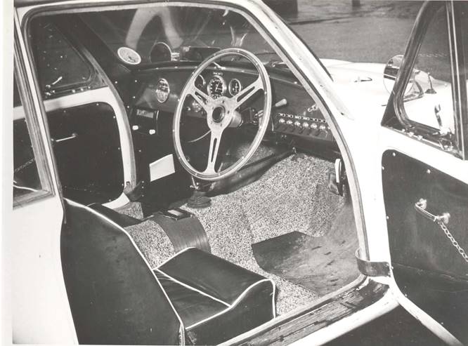
In the photo of EBV 358, complete with lady driver,
it's just possible to make out the standard Rochdale dash layout with the
instruments in the centre and untrimmed glassfibre windscreen pillars. The car
has the flat floor with low, but wide, seats and as can be seen, headroom even
for the lady driver is minimal! Also visible is an old-type electric windscreen
wiper motor simply mounted through the dash in front of the steering wheel
effective, but not very pretty. These motors, as fitted to quite a few
1930s-50s cars, were operated by a switch on the casing, so needed to be
accessible. One modern item on this GT is separate flashing indicators, and
these appear to have a column switch, below the wiper motor.
KS 101 which, like EBV 358, was photographed in
Rochdale and was a car well known to the factory goes to the opposite extreme
and I would be interested to know what chassis was under this car. It's
certainly not the Ford chassis, as the body flange just inboard of the doors
that bolts to the top of the chassis has been cut away and the car has neat,
flat floors two or three inches lower than the normal position, with a
commensurately higher transmission tunnel. Neat period accessory seats are used
and the interior is very neatly carpeted. Door, footwell side and screen side
panels appear to be glossy so are probably painted there is no rough
glassfibre visible anywhere and a full-width varnished wood dashboard is
fitted.
EVB
358 Note minimal headroom, even with lady driver
KS 101 - A highly specified
car
No expense has been spared on this car which has a
lovely wood and alloy steering wheel and a valve radio set over on the far
side. Sturdy leather door check straps are fitted, as are stainless steel door
window frames from the Morris 1000 Traveller and chrome interior door handles
with chains to the interior door handles. The Ford Pop umbrella handbrake is
neatly tucked in on the far right under the dash, where hopefully you won't
catch your knee on it when getting out (a common problem on early P4 Rovers).
There's a smart chromed remote gear linkage, a good set of centrally-mounted
instruments, a column switch for the indicators and a bank of minor switches to
the right of the steering column. There's even an ashtray set into the
transmission tunnel!
NBN 115 was another high-spec car, but not to the same extent
as KS 101. This one is on the Ford Pop chassis with standard floors and painted
door tops. Nice touches are the wacky bucket seats, chromed remote
gearchange, centrally-mounted handbrake, wood/alloy steering wheel and
comprehensive instrumentation in a dashboard that has been built out and bears
no resemblance to the standard offering. Flat rexine-covered door trims have
been fitted and it looks as if a white headlining has been fitted and brought
down the screen pillars to the top of the dashboard. Furflex door seals are
fitted, too.
HG 6688 is a very well thought out,
attractive and relatively inexpensive interpretation. It has a
late 103E steering wheel and its instruments which appear to include the Ford
speedo and fuel gauge with an ammeter and a dual oil/water gauge added are
mounted to a board set over the standard moulding and hooded, so that
illumination is provided from a bulb behind the curved hood. On either side
wood (or more likely Formica!) glove box lids are fitted, with a grab handle
for the passenger, very tidy carpeting with rubber heel mats and
colour-coordinated seats, door trims, footwell side trims and screen pillar
trims. A gutter has been fitted to the outside of the door opening as well as
Furflex door seals. Again, a remote control gear linkage is used, this time a
simpler painted one but neatly set off with a gaiter matching the trim. An
internal door handle is fitted with below it a trimmed door pull strap. The
Ford handbrake is used, but this time mounted low down to the left of the
footwell to avoid the knee risk. The only thing I haven't managed to identify
is the round black blob immediately above the internal door handle.
I hope these give some inspiration to everyone
contemplating how to trim a GT!
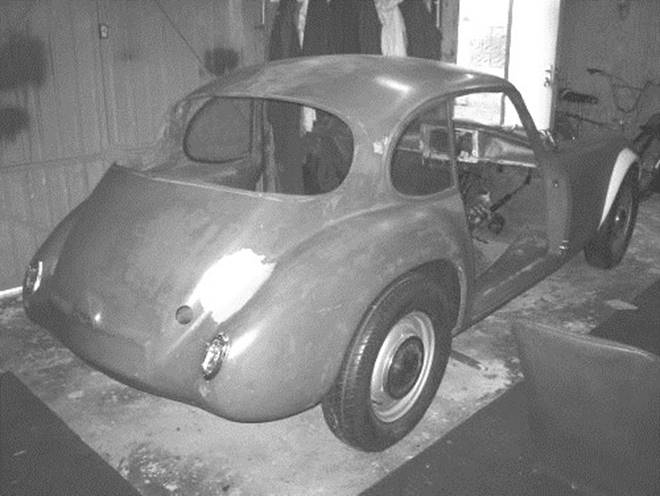
Lost GTs
resurface
I hadn't heard from HFJ 886 since it was rescued by
Chris Lane 10 years ago and handed over to his friend C Bent. I suspect it's
still in the same ownership, as it was spotted in the Forest of Dean last year
by Turner owner Nigel. At first glance, it appears little better than 10 years
ago, apart from the removal of the ugly pair of spotlamps that had been mounted
on top of the nose, but a closer look at the rear view shows shiny silver/red
wheel and hub that suggest the running gear may well have been nicely restored,
just (!) leaving the body and interior to do.

Also in the Forest of Dean (a great haven for
Specials!) is Granville Phillips GT, a very high spec car that, back in 1958,
featured in Rochdale Motor Panels adverts for the GT. Granville found the car
covered in snow lying in the corner of a field about 20 years ago and has since
restored it twice, having had several setbacks along the way. I don't have the
full spec sheet to hand for the car, but recall it had a Willment
inlet-over-exhaust cylinder head with twin SU carburettors, independent front
suspension, telescopic dampers and plenty more.
The car now runs and drives but still needs spraying
and a complete interior fitting out. It comes with lots of spares including a
wooden dashboard and, if the work has continued to the same high standard as I
saw when I visited Granville about 15 years ago, I'd say it's worth the £2000
he's asking. If you think that's a lot, bear in mind that the last Willment
head seen, an incomplete kit on sale at Beaulieu last September, was priced at
£1500. And I don't want to hear that this historic Rochdale has been robbed for
some jumped-up Lotus Six replica
If you're interested, give Granville a ring on 01989
768369 or 07917 152065 and do check that the Willment engine is still in the
car, as he didn't mention it when he rang to say he was selling. Without that,
sadly, it's probably not worth the asking price.
Worlds most
valuable GT
The GT that made a record price on ebay last year,
heading to Japan from USA, has rather surprisingly changed ownership within
Japan but I'm delighted to welcome new owner Hideki Saka of Hiroshima. As the
photograph shows, Hideki is a Lotus fan with a couple of fine Elans already in
his collection. Hideki is very keen to get the GT into 100% correct order and
has asked for help in reinstating the original number plate light plinth. At
some time in its history, which included being exported from UK to Holland in
the 1970s where it was restored and maintained in superb condition for decades
by Bert Tressel, the car lost its original rear number plate light and was
fitted with lights at each end of the plate.
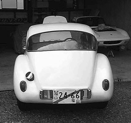 This is not an
uncommon problem for GTs as, without bumpers, the number plate light is the
most prominent part at the rear of the car and any rear impact tends to push
the light and a section of glassfibre behind it into the boot. I suspect that, when
this car was restored in Holland, the plinth and light had been broken in such
a way and had disappeared, so the restorer glassed in the hole to match the
surrounding profile then wondered where to put number plate illumination
This is not an
uncommon problem for GTs as, without bumpers, the number plate light is the
most prominent part at the rear of the car and any rear impact tends to push
the light and a section of glassfibre behind it into the boot. I suspect that, when
this car was restored in Holland, the plinth and light had been broken in such
a way and had disappeared, so the restorer glassed in the hole to match the
surrounding profile then wondered where to put number plate illumination
Thankfully, Dave Milner has come to the rescue,
tidied up the plinth area of his GT and taken a splash moulding off it. He's
kindly promised me a moulding of the section too, as the same problem has
befallen my own GT at some time in the 35 years it's been off the road thanks,
Dave!
School Project
GT
Club member and Olympic driver Les Brown spends his
working hours teaching IT in a secondary school and deserves all our admiration
for investing a good deal of spare time into teaching the boys a bit of classic
car restoration, using a Rochdale GT as the subject!
Les and the boys have been making steady progress
over the last year or two and at last the project is really come together, with
the body gleaming in hand-brushed coach enamel. This GT is on a modified
Triumph Herald chassis, fitted (just to make life difficult?) with a Morris
Minor engine and looks likely to be a very fine car when finished well done
Les and all the team.
Les remarks:
"I've been concentrating on the GT lately, with
time running out to finish it before retirement. Seats are in, steering's
working, paint's mostly done (coach enamel - bright red) brakes are on,
carburettors next and I ain't looking forward to all those electrics. Kids keep
on about making Capesthorne but I have my doubts!"
Surely not, Les we're confident you'll make it! I
was terrified by electrics too before I bought my first GT. It had no wiring
loom in it, so I bought several big rolls of wire and a load of connectors from
my local accessory shop and set about wiring it up. It's quite simple really
when you do it that way, because you can deal with each item in turn, take a
wire from the light or whatever to the switch (and another to earth), then
power to the switch from the appropriate side of the fuse box, etc.
Try to route the wires together and, when they're all
done, bind them together neatly with black insulating tape or self-amalgamating
tape (see note below Ed). In an ideal world you'd use the
same colour-coding as other cars but on such a simple car you can get away with
just using three colours blue for lighting, red for live, black for earth
or if you've access to more colours, go for the standard pattern of
black-earth, brown-live, yellow-charging, blue-headlights,
white-ignitioncontrolled live wires. Taking a wiring loom out of another car
and stripping it for the exact correct colours is another option, but very
labour-intensive and fraught with problems such as damaged wires or ones that
are too short. Good luck, Les!
Note: I have done a lot of wiring
recently and wouldn't recommend either of these, Malcolm. It's better to use
the correct PVC harness tape, which can look really smart if done neatly. It
does not get sticky like insulating tape and is much easier to apply than
self-amalgamating tape, which needs real skill. Alternatively, use split
convoluted sleeving to cover bundles of wires, as applying tape of any sort is
a slow job. Braided sleeving gives a period look but needs planning. If you
use crimped connectors use a proper ratchet crimping tool (about £20) not the
Mickymouse sort usually offered. If you use bullet connectors for authenticity
always solder the ends rather than poking the wires in and hoping for a
miracle. Also, smear a little copper grease on the bullets before fitting to
combat corrosion. Heatshrink tubing is also very useful for covering soldered
joints etc. A heat gun is necessary for this; I have seen hair driers
suggested for this job though I wouldn't want to put my head under a hairdryer
that can shrink tubing!!!
All this stuff and lots more can
be obtained from www.autoelectricsupplies.co.uk, whose online shop is a doddle to
use. Usual disclaimer. Alan Farrer

The MM engine in Les Browns GT

FBHVC NEWS
DVLA
Sandy Hamilton
I had hoped that the April 2004 consultation on
inspection procedures was in the past but the September 2005 publication of
responses to it seems to have caused confusion amongst some enthusiasts and
certain of the specialist press. The following comments are intended to lay to
rest the fears and anxieties that some of the scare-mongering stories have
generated amongst those inclined to believe in conspiracy theories.
The original consultation was a ten-year review of
procedures first introduced in 1994 following earlier or consolidating
legislation. This had included establishment of Single Vehicle Approval (SVA)
testing for imported and amateur/kit-built vehicles. In essence, the
consultation wanted to establish whether the procedures had been effective,
were they working properly or did they need improvement and/or amendment. If
they were considered satisfactory that was OK, since there was no hidden agenda
to sneak yet more restrictions upon us.
Replies were to be submitted by July 2004 and,
following digestion of the 431 individual responses, DVLA published their
analysis in September 2005. It was at this point that some parties began to
huff and puff and to circulate stories that any modification (even changing
seats or brakes) would render a vehicle liable to an SVA test, removal of
historic status (if applicable) and re-registration with a 'Q' mark - or worse
- removal from the road.
Cutting through the hysteria it seems that those most
concerned had missed the introduction of the new procedures in 1994 or, if they
had been aware, had not fully understood the nature of the 2004 review
consultation. Their fears sprang from selectively reading the 'recommendations'
that were attached to each review category. These were in fact a summary of
respondents views expressed in their replies, and were not those necessarily
supported by DVLA. Indeed these recommendations were to be subject to further
analysis and review and only those that had merit, or could be cost-effectively
introduced, would be subject to formal proposals and further consultation.
Having spoken to the relevant departments at DVLA I
am assured that no recommendations are being acted upon that would give rise to
some of the wilder theories about extension of SVA testing, withdrawal of
registration marks, or restrictions on use, or the ability to undertake vehicle
modifications. DVLA has no desire to be informed when you have changed to alloy
wheels, added spotlights, new seats, disc brakes etc. The only changes that you
are obliged to inform are those that are annotated on Section 7 of the V5C
document and that affect identification (personal and vehicle) and have
potential VED revenue implications.
A caution is that unregistered vehicles built from a
variety of spare parts ('rebuilt classics') may need to obtain certification as
to the age of components and to obtain confirmation from a recognized club
prior to being allocated an appropriate age-related mark. In those cases a
radical departure from the original specification may require a DVLA inspection
to establish how much of the original design is retained. The principal
category potentially affected would appear to be extreme customisation where,
for example, 'chopping and channelling', changes to design of suspension and
steering so radically affect the appearance that the vehicle no longer
resembles the original outline or style. For avoidance of doubt the above is a
summary of existing requirements since 1994 and is not new. Very if any few of
'our' vehicles are likely to be affected by this process and any vehicle in possession
of a valid logbook (VSNSC) does not require to follow it.
Rest assured that FBHVC will continue to monitor
these consultations to ensure that any action that may follow does not
adversely affect our movement. In the meantime continue to attach furry dice to
your vehicles without fear that cameras will record your crime and impose a
penalty for non-reporting!
MOT Test Procedures
We continue to receive comments that the computerised
MOT test procedures have given rise to new restrictions or removal of data,
such as obsolete makes/models. In most cases DVLA is blamed for these problems.
While their database is not perfect, upon examination we have found that the
problems are caused by lack of relevant technical information on the VOSA database
or a test examiner's unfamiliarity with the newly installed system, e.g.
ability to cancel/re-input incorrect data. We repeat our advice to double-check
the vehicle description and numbers to ensure that what the tester records is
on the V5C. If not correct, make sure the changes are done before your test.
Much adverse comment has come from the so-called
'abolition' of the free re-test. That animal never really existed but grew from
a practice that, at best, was customer-service related but more likely was
'tester-effort' biased. VOSA has recognised there is a genuine requirement for
rectification of modest faults without incurring a full fee and is taking steps
to put this in place. It is up to each Testing Station to decide the level of
fee, up to a maximum, in this category.
We repeat our advice that owners should undertake a
preMoT inspection of their vehicles rather than continue the habit of many of
using the MoT test to tell you what servicing work is needed. This could become
an expensive habit if not corrected!
Renewal of Car Tax
(VED)
Finally, a piece of welcome and up-to-date news. It
is now possible to renew your VIED disc through the Electronic Vehicle
Licencing (EVL) facility that has just been announced following a successful
pilot programme in several areas.
This can be done via the telephone at 0870 850 4444
or by logging on to www.direct.gov.uk/taxdisc. All keepers of vehicles less than three years old can use
ELV while those subject to an MoT test will need to have a computerised MoT
certificate. (It is anticipated that all MoT testing stations will be
operational by the end of March 2006 so all licensed vehicles should be able to
use ELV by 2007). There is no need to present paper insurance or MoT
certificates as the process is handled electronically; the VED disc will be
despatched by post and received within 3-4 days.
Access to a phone or computer will enable -a
keeper to apply for a VED wherever they may be, at home or abroad, 24 hours per
day and seven days per week. SORN may also be declared electronically so the
new ELV procedures should answer the vast majority of concerns we have heard
from members who travel both frequently or extensively. As always, we welcome
feedback from members who have had experience of ELV whether or not it is
favourable.
DRIVE IT DAY - 23 APRIL
FBHVC urges all owners of licensed historic vehicles
to use them on 23 April - every year. This will be a truly national annual
event and one that all enthusiasts can take part in,
wherever they live. It's absolutely free of entry forms, fees and red
tape.
It's not necessary for owners to go to a show or to
take part in an event, FBHVC just wants owners to get their vehicles out so
they can be seen by the public. If the vehicle is suitable, it could be used
instead of modern transport for daily activity. Owners could use them to go to
work take a trip to the seaside, enjoy a day out in the country, visit a
stately home or just go shopping.
For those with unlicensed, older, larger or slower
vehicles for which such use would be impossible, impractical or inappropriate,
owners could at least get them out and park them on the drive where they can be
seen.
FBHVC exists to uphold the freedom to use old
vehicles. Drive It Day is part of an ongoing campaign to raise public
awareness of the historic vehicle movement. After all, Tony Beadle (the
committee member who came up with the idea) asks, what's the point in fighting
for a freedom if we don't make the best possible use of it?
OLYMPIC PHASES
Most Rochdale owners will be familiar with the fact that
there were two major variations with the Olympic, the phase 1 and the phase 2.
Some will even have heard of a phase 1. and assume that this was an
intermediate model. This is a bit misleading as such a model never officially
existed. I will attempt to explain my understanding of the models produced and
the major differences between them. Of course, the phase 1 was never
officially called a phase 1 until the phase 2 had been introduced.
The first production shells were noticeably different from
subsequent Phase 1s in the following respects. The bonnet was smaller, being
only 30.5" at its widest point compared to 34.5". The shape of the rear edge
of the bonnet was also different, being more or less straight rather than
following the curve of the windscreen. This left no space for a heater intake
opening. The photo in the Motor Road Test indicates this quite clearly. On
the early shells the front sub-frame is also different in that the B series
engine is mounted from the inner wing panels with a bonded in tubular framework
and not from the sub-frame. A number of the internal mouldings are slightly
different. Very few of these early shells were produced, but at least five are
known to have survived. Three versions were available for Riley/Wolseley,
Morris Minor or Ford 10 components.
After the factory fire it was necessary to remake the
moulds and I have always assumed that it was at this point that point that the
changes were made to produce the phase 1 shell that most of us are familiar
with. The front sub-frame will vary slightly, depending on whether it was supplied
for Riley/Wolseley or Morris Minor components, as the steering rack is
different. Initially, all engine mounts were from the inner wing panels,
although at some point fairly early on the B series engines were mounted from
the front sub-frame.
Two different kits were available, the Riley version at
£670 and the Morris Minor version at £598. The Ford 105E engine was an option
with the Minor kit at no extra cost. Incidentally, when the 105E engine was
supplied the mountings from the inner wing panels were retained. This was no
doubt due to the fact that the Ford mountings were half way along the side of
the block and not at the front as with the BMC engines.
During the latter part of 1962 a revised version of the
Olympic was under development. This was introduced to the public at the Racing
Car Show in January 1963. Substantial modifications were made, to the extent
that very few major components or mouldings are interchangeable. However, as
the external silhouette remained the same some part panel mouldings can be used
to repair either phases.
The most noticeable of these changes externally was a
larger bonnet, opening rear hatch and cut away rear panel to allow mounting of
a spare wheel underneath. The changes however went much further and consisted
of a revised front sub-frame to suit the Triumph based suspension, fully ducted
radiator and open transmission tunnel rather than the full length undertray of
the phase 1. The rear suspension also changed to tapering box section trailing
arms and full width panhard rod to locate the rear axle. Internally the
mouldings were modified with a new dashboard and thinner doors giving increased
interior width. The two small rear seats also disappeared being replaced by a
flatter load area.
The Phase 2 with 1500cc Ford engine sold for £755, with the
GT engine a £40 extra. Initially the phase 1 kit could still be obtained as a
cheaper alternative. However, there were increasing supply problems with BMC
components and before long the phase 1 would only be available as a
body/chassis unit at a cost of £256.
Whilst the phase 2 was under development one or two phase
1s were either supplied or retro fitted with an opening hatch by the factory.
This process has continued in latter years and a number of phase 1 shells have
been subsequently converted.
By the mid 1960s Harry and Frank had obviously decided that
the Phase 1 moulds were not good enough to use. Hence if a customer
particularly wanted to use Morris or Riley components he would be supplied with
what was essentially a Phase 2 shell, with Phase 2 rear suspension, but
different front sub-frame to take the BMC components. The cost for this option
was £271. By this time production of the Olympic had slowed down to a trickle
and the literature was not reprinted, but merely amended by hand. The cost for
the phase 2 kit had increased to £780 and the Ford 1500 engine replaced by the
1600 cross flow engine.
The above is my own understanding of the Olympic variations
produced by Rochdale Motor Panels, but I stand to be corrected if anyone knows
differently.
Derek Bentley
PART No.
RS 1
|
Material:
Polyurethane
Application: Ph 1
Panhard rod axle end; Top shock absorber
Ph
2 Panhard rod body end; Rear shock absorber lower; Anti-roll bar link
upper
|
|
PART No. RS 2

Application: Ph 2 front suspension pivot
PART No. RS 3
Material:
Polyurethane with removable stainless steel sleeve
Application: Ph 2
Panhard rod axle end
|


Copyright © Rochdale
Owners Club
Last Update